Eliminating Condensation in Pneumatic Drive Systems in Modern Paint Operations



Introduction
Compressed air has been used as a power source in industry for many years. Two of the most familiar are construction – where it is used to drive nails and staples and to cut, shape and sand both wooden and metal parts – and in automotive repair shops where it drives impact wrenches, die grinders, orbital sanders and spray guns in the paint booth. Pneumatic motors generally provide greater force than their electrical counterparts of similar size, resulting in small, powerful hand tools with no shock hazard.
Powering the Modern Paint Shop
Everyone’s first thought of compressed air use in painting operations is for spray guns. While true, the non-electrical aspect of compressed air drive is perhaps even more useful. Properly constructed pneumatic motors are naturally intrinsically safe, allowing them to be used in explosion-proof environments without all of the hassle and expense associated with safely running electrical systems in these settings. This makes them ideal for powering the agitators and pumps used to mix and distribute paint. Moreover, in most modern painting operations, spray bells are used equally, if not more often than spray guns. For the uninitiated, these devices use a pneumatic motor to spin a cup or disk at high speed. When the paint is injected onto the surface of this spinning cup/disk, the centrifugal force atomizes the paint, creating a “fog” of very evenly sized droplets, which can then be transferred to the target part to create a smooth, even finish.
Of course, with all benefits come drawbacks. In the case of pneumatic drive systems, the inherent safety is offset by the noise and cooling generated when a compressed gas is released.
The Cooling Effect
The cooling effect is the result of the Ideal Gas Law. This fundamental law of physics states that the pressure and volume of a gas are directly proportional to its temperature. The formula can be expressed as PV = nRT, where:
Pis the pressure of the gas
Vis volume the gas occupies
nis the number of moles of the gas
Ris the ideal gas constant (8.314 J*K−1*mol−1), and
Tis the temperature of the gas
A simple balloon provides the best example of this relationship. Say you purchase a balloon at the fair on a hot summer day. It is a certain size based on the pressure of the rubber shell pressing on the volume of air blown into it, and is at the temperature of the air on that warm day. Now suppose that you take it home to your air-conditioned house. As the air in the balloon falls to the indoor temperature, the pressure and volume decrease together to offset the change in temperature – and the balloon gets smaller and softer. Take it back outside and the process reverses itself and the balloon returns to its original size and firmness.
So what does this have to do with your paint shop? The air coming into the motor is compressed within the volume of the hose that is supplying it. It is also basically at room temperature. As the air passes through the motor, it is released into the room. The volume expands and the pressure falls to match the atmospheric conditions of the room. When this occurs, the value of the left side of the equation drops (as the pressure falls toward 0 PSIG), and in response, the temperature of the compressed (or more accurately “the no-longer-compressed”) air falls to balance the equation and all is right with the physicists of the world. As this process continues, the cool air draws energy from the surfaces of the motor around it and the motor gets cooler.
So why is this a problem? Frankly, it isn’t – not until the temperature of the surfaces of the motor fall below the dew point of the air in the room. Then everything changes.
The Dew Point
It turns out that paint shops are generally areas of high humidity. Some even use waterfalls to catch overspray. As the humidity increases, so does the dew point – the temperature at which water condenses out of the surrounding air. We’ve all seen this on a soda can fresh from the refrigerator.
Calculating the approximate dew point is actually quite easy. If you know the temperature (°F) and the relative humidity (%), the dew point will be:
, where:
Tdpis the dew point temperature
Tis the temperatureof the room (in °F)
RHis relative humidity if the room (in %)
For the purposes of this article, let’s assume a summer day when it is 86 °F and 65% RH in the paint booth. Based on this formula, when a surface falls below 73.4 °F, water will begin to condense on it from the surrounding air (not the compressed air). In application, this manifests itself in many ways.
The Problem with Condensation
Noise is always a concern in industrial environments and, in the case of air drives, this is addressed by placing a muffler on the exhaust port. Dispersing the air to reduce the noise results in a concentration of both condensation and cooling in the muffler that can cause ice formation – sometimes severe enough to completely stop the device. This is a common problem with pumps and agitators.
The real issue, however, occurs when the condensation comes in contact with the painted surface. This is where we will focus the balance of our attention.
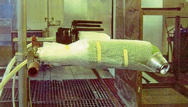
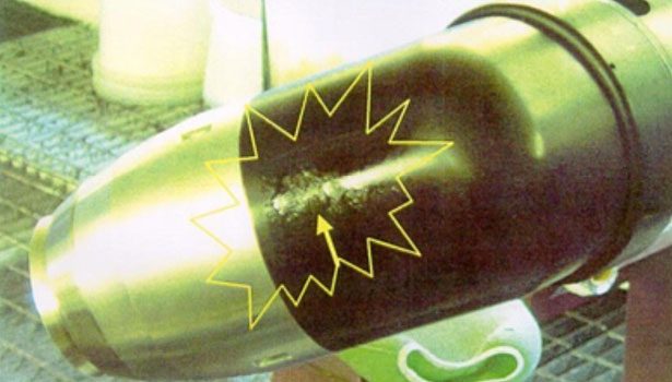
Picture 1, shows a bell in position in a paint booth. As in the example provided above, this bell was operating in an 86 °F, 65% RH environment with a dew point of 73.4 °F.
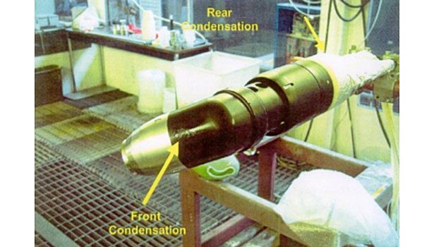
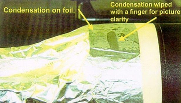
Picture 2 shows condensation forming on both the front and the rear of the housing. These are shown in greater detail here in Pictures 3 and 4.
The formation of condensation can be predicted in any area where the surface temperature is below the 73.4 °F dew point. These points were measured as shown in Figure 1. As the condensation forms, it builds up on the housing, eventually rolling off to land either directly on the painted surface or on the rotating disk itself where it is then “spit” onto the painted surface along with the paint. These defects result in rework or scrap.
The Solution
The solution really is as simple as it appears – assure that surfaces of the bell never fall below the dew point temperature so that condensation cannot form.
One solution would be to add a heater into the bell housing. Being in an explosion-proof environment, however, this would require a complete redesign of the bell housing to incorporate both an intrinsically safe heater and wiring into it. This is not practical.
Another solution is to heat the compressed air being fed to the existing bell. This can be accomplished by inserting a heat source into the compressed air supply line ahead of the bell. This, too, presents challenges.
If the heater is placed on the compressed air supply outside the intrinsically safe area, it will be ineffective. The reasons for this begin with the properties of the air itself. Under normal circumstances, air has a low specific heat (0.24 BTU/lb °F) and a very low density (0.08 lb/ft3). When compressed, that density increases to 0.6 lb/ft3. From this, we can show that just one BTU of energy will change one cubic foot of compressed air by 7 °F!
With the heater located outside the intrinsically safe area, the air must run through as much as 50 to 70 feet of tubing before it finally reaches the bell. If 70 feet of standard 3/8” supply hose is run from the heater to the bell, it will contain a total volume of just 0.05ft3 of compressed air. If the compressed air is heated to 110 °F in the example shown above, it has to drop 36.6 °F to reach the dew point, but this equates to a loss of just 0.3 BTU!
Therefore, to be effective, the heating source must be placed in the booth very near the bell. Because an electric heater element is the most fundamental of ignition sources and it is being placed in an area laden with a solvent/air mixture, this will require an intrinsically safe heater and intrinsically safe wiring practices to connect it. These are very expensive, and most in-line electric heaters are designed for heating fluids – not air. So, this, too, appears an impractical solution.
SCS’ Patented Approach - The Solution Made Simple
SCS applied its 25 years of temperature control experience to the problem to arrive at a solution that is simple and safe, yet innovative enough to be granted Patent #7,322,188.
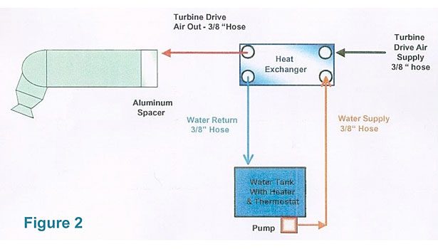
This approach is shown in the functional diagram in Figure 2. By using water to heat the compressed air, instead of electricity, the temperature control can be placed at the point of use (the bell) while circumventing the intrinsic safety issue by locating the electric heating elements, which warm the water, outside of the explosion-proof area.
The system employs a small water-to-air heat exchanger (3” x 8”) that can be mounted on the same arm as the bell, shortening the distance that the warm compressed air travels to just 18” – 24”. A specialized coating both insulates the HX and limits dirt build-up, making it easy to clean. A small temperature control unit (TCU) comprised of a reservoir, heater, pump, and controller is located outside the booth in a non-explosion-proof area. This both regulates the water temperature and circulates it through the heat exchanger. In this configuration, the air is heated just prior to entering the bell and raises the surface temperatures of the bell, as shown in Figure 3.
Clearly, the heating of the compressed air is sufficient to maintain the temperature at the exhaust, and at all other points in the system, safely above the dew point in spite of the cooling effect documented above. Based on this data, we would expect that there would no longer be any formation of condensation anywhere on the bell housing.
In Pictures 5, 6, and 7 we can see that, after a full hour of operation, there is still no condensation forming anywhere on the housing. Clearly, the condensation problem has been solved – permanently.
Similar results have been demonstrated with pumps and agitators, as well, showing this to be a viable solution for any pneumatic drive condensation problem.
Looking for a reprint of this article?
From high-res PDFs to custom plaques, order your copy today!


