Hard Surfacing on a Steel Punch Using Direct Metal Deposition

Improvement in the performance of a cylindrical punching tool for hardness and wear resistance was tested after the use of direct metal deposition (DMD) to deposit an additional material on the tool surface. DM3D Technology has been working for several years improving the DMD technology, which is capable of melting gas-atomized metal powders with a power laser over a substrate layer by layer. The technology allows the possibility of using one or several materials to build a 3D part, repair an existing component or deposit over a surface to obtain desired properties. Some of the main characteristics of this technology that distinguish it from others is its capability of allowing fully dense metal structures, controllable microstructures, and heterogeneous material fabrication as well as near net shape geometry generation.
Figure 1 shows a general overview of a DMD system that contains a laser system, a powder feeding system, shielding and cover gases for oxidation and transportation of powders, and feedback sensors to control the deposition process. Particularly for the purpose of the experiments described in this paper, a DMD machine with a CO2 laser controlled by a three-axis CNC system from DM3D Technology was used.

|
| Figure 1 - Direct Metal Deposition |
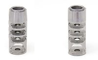
The punch1 used for this case study was originally made out of a tool steel with a hardness of 54 HRC [1, 2], and in order to increase its service life, a higher carbon content tool steel−to improve wear resistance and even further the toughness−was deposited by DMD. A complete part body, indicating the top face area where the high carbon steel deposition was made, is shown in Figure 2. Due to the nature of this process, the surface roughness usually is as good as a sand casting; therefore, depending on the specification of the part, some finishing can be done afterward.

|
| Figure 2 - Punch and Deposition View |
Results:
A metallographic analysis was performed on a cross section of the punch to show the full metallurgical bond between the punch and the high-carbon steel. In this analysis, an average deposition thickness of 544 µm was found (observed in Figure 3), which shows the right corner from the two edges of the cross section analyzed.

|
| Figure 3 - DMD cross sections |
Some characteristics found in this analysis were a fine grain structure and an improvement in hardness by 10 percent compared with the tested hardness on the current tool steel. Figure 4 shows the harness behavior along a diagonal line from the edge of the punch left corner section. The different harnesses show consistency in most of the deposition, which gives confidence for DMD to control the microstructures.

|
| Figure 4 - Hardness test |
With considerably improved hardness, the treated punch will show an increment on its compressive strength, which benefits its tool life. This material addition not only works as an improvement to the tool steel toughness but also to wear resistance. The minimum heat-affected zone between the two alloys showed that the properties of the original punch were as close as the material specification immediately after the interface.
Wear behavior was tested on the post-DMD punch as compared with standard tool steel. Experiments were carried out in a pin-on-disk setup under 30 N (∼6.7 lb) load and 22.15 m/min. (∼872 in./min.) speed at room temperature. These results showed a reduction of 80 percent in depth of wear between the two punches and can be observed in Figure 5.

|
|
Figure 5 Punch wear behavior |
Results like this show DMD to be a value-added technology that can lead to considerable cost reductions by allowing a component to be built with a non-expensive alloy and adding the required alloy only on the needed areas. This concept can be easily applied on used and worn components to increase tool life.
In conclusion, the main advantages of DMD technology for hard surfacing over conventional manufacturing processes are:
The ability to add dissimilar materials, allowing different properties on desired areas, resulting in cost reductions;
Low heat-affected zones; and
Low distortion of the part due to laser low heat input.
1 The tool steel punches used were supplied by Dayton Lamina Corporation.
2 Difference obtained from an average substrate hardness tested of 58 HRC and high carbon steel average hardness of 63.9 HRC.
REFERENCES
[1]http://www.matweb.com/search/DataSheet.aspx?MatGUID=e30d1d1038164808a85cf7ba6aa87ef7&ckck=1, date of access January 8, 2015
[2] http://www.daytonlamina.com/node/1114, date of access January 8, 2015
[3] Qvarnström, Hans (1989). Technical Note: A mathematical formula for transformation between the steel hardness scales of Rockwell C and Vickers. Journal of Heat Treating, v7, n1, pp65-67, http://dx.doi.org/10.1007/BF02833189.
Looking for a reprint of this article?
From high-res PDFs to custom plaques, order your copy today!


